What do you see?
Colours are Logisim's own defaults. They can be changed in Preferences, and some courses change them for colour-blind students. Every swatch carries its letter.
Red wire, E value: E
Two outputs drive the same wire with different values, or an error value is travelling along it. Equal values give that value.
Likely causes, most common first
- Two outputs on one wire that disagree. F07
- Two enabled buffers on a shared bus with different values. F10
- A feedback loop with no stable state. F06
- An error coming out of a subcircuit.
How to find it
- Trace back from the red wire to every output pin or gate output attached to it.
- Tunnels with the same label count as the same wire.
- Open each subcircuit and look for red inside.
Fix
- Remove one driver, or select between them with a multiplexer.
- On a shared bus, use Controlled Buffers and enable only one at a time.
- Do not delete wires until the colour goes away: find the second driver.
We tested this in Logisim-evolution 5.0.0 (F07, F10).
Full section belowControlled BufferTunnelsSubcircuits
Not this? Try
All colours at a glance
| Colour | Value | Meaning | Most common cause | First fix | Evidence |
|---|---|---|---|---|---|
| Bright green | The wire carries 1 | Normal | None | F03 | |
| Dark green | The wire carries 0 | Normal | None | F03 | |
| Black, thick | bus | A wire wider than one bit | Normal | None | Logisim default |
| Blue | Nothing drives the wire | Wire end not on a port | Reconnect it | F08 | |
| Red | Drivers disagree, or an error | Two outputs on one wire | Remove or select between them | F07, F06 | |
| Orange | Bit widths differ | 4-bit wire into a 1-bit pin | Match Data Bits | F09 | |
| Grey | no value | Not shown yet | File just opened | Click the canvas or press Ctrl+R | F45, F49 |
Only red, blue, orange and grey need action. The other rows are the circuit working.
The same Logisim-evolution 5.0.0 window after the simulation was reset. The first wire is bright green with pin value 1, the two wires driven by two outputs are red with E, the wire nothing drives is blue with U, and the width-mismatch wire stays orange.
You can open the same four cases as circ-wire-colors-showcase.circ and compare its command-line table with the one we captured (see Downloads below).
Red wire and E: two outputs disagree
When two outputs drive one wire, Logisim compares what they send. If the values are equal, the wire carries that value. If they differ, the wire is red and reads E (F07). Our smallest case ties two input pins to one wire and asks for the table:
| # | A | B | Y |
|---|---|---|---|
| 0 | 0 | 0 | |
| 0 | 1 | E | |
| 1 | 0 | E | |
| 1 | 1 | 1 |
Describe this circuit
Components: Input pin A; Input pin B; Output pin Y.
- Input pin A connects to Input pin B, Output pin Y (net A, B, Y).
Find the two drivers
Start at the red wire and follow it to every output attached: pins that are inputs to the circuit, gate outputs, subcircuit outputs and constants. Tunnels with the same label count as one wire, so a driver can be far from the red wire on screen (see Tunnel). A splitter can also join two outputs you did not mean to connect.
To fix it, remove one driver, or put a multiplexer in front so that only one source drives the wire:
Describe this circuit
Components: Input pin A; Input pin B; Input pin Sel; Multiplexer 1; Output pin Y.
- Input pin A connects to Multiplexer 1 (net A).
- Input pin B connects to Multiplexer 1 (net B).
- Input pin Sel connects to Multiplexer 1 (net Sel).
- Multiplexer 1 connects to Output pin Y (net Y).
Shared buses: use Controlled Buffers
A shared bus is the one place where several outputs on one wire is the design. Each source goes through a Controlled Buffer, which puts nothing on the wire when its control input is 0. Our two-buffer circuit gives this table (F10):
| # | A | B | SelA | SelB | Y |
|---|---|---|---|---|---|
| 0 | 0 | 0 | 0 | U | |
| 0 | 0 | 0 | 1 | 0 | |
| 0 | 0 | 1 | 0 | 0 | |
| 0 | 0 | 1 | 1 | 0 | |
| 0 | 1 | 0 | 0 | U | |
| 0 | 1 | 0 | 1 | 1 | |
| 0 | 1 | 1 | 0 | 0 | |
| 0 | 1 | 1 | 1 | E | |
| 1 | 0 | 0 | 0 | U | |
| 1 | 0 | 0 | 1 | 0 | |
| 1 | 0 | 1 | 0 | 1 | |
| 1 | 0 | 1 | 1 | E | |
| 1 | 1 | 0 | 0 | U | |
| 1 | 1 | 0 | 1 | 1 | |
| 1 | 1 | 1 | 0 | 1 | |
| 1 | 1 | 1 | 1 | 1 |
Describe this circuit
Components: Input pin A; Input pin B; Input pin SelA; Input pin SelB; Controlled Buffer 1; Controlled Buffer 2; Output pin Y.
- Input pin A connects to Controlled Buffer 1 (net A).
- Input pin B connects to Controlled Buffer 2 (net B).
- Input pin SelA connects to Controlled Buffer 1 (net SelA).
- Input pin SelB connects to Controlled Buffer 2 (net SelB).
- Controlled Buffer 1 connects to Controlled Buffer 2, Output pin Y (net Y).
Rule of thumb: at most one buffer enabled at a time. If the enables come from a decoder, check that it can never enable two at once.
Red from a loop
A feedback loop with no stable state also shows E and a red loop (F06). That is oscillation, and it has its own fix guide: see Oscillation apparent.
Logisim-evolution 5.0.0 canvas with a NOT gate whose output wire loops back to its own input. The wire is red, and the output pin Q shows E.
Red that spreads from a subcircuit
An E inside a subcircuit comes out of its output pins, so the red may be far from the cause. Open the subcircuit (double-click it in the circuit list, or use Simulate, Go In To State) and look for the red wire inside. See Subcircuits.
Blue wire and U (or X): nothing drives it
A blue wire has no driver. In Logisim-evolution 5.0.0 its value is U; older documents and many course sheets call it X. It is the same state (F08). In our test the output on an undriven wire read U for every input, while the output next to it still followed its input:
| # | A | Y | Z |
|---|---|---|---|
| 0 | U | 0 | |
| 1 | U | 1 |
The wire end is not on the port
This is the most common cause. A wire that stops one grid step short looks connected but is not. In Logisim a connected end shows no gap and a junction dot where wires meet. To check, drag the component a little and watch whether the wire follows, or click the wire end and look for where it stops.
Describe this circuit
Components: Input pin A; Output pin Y; Output pin Z.
- Input pin A connects to Output pin Z (net A, Z).
Describe this circuit
Components: Input pin A; Output pin Y; Output pin Z.
- Input pin A connects to Output pin Y, Output pin Z (net A, Y, Z).
An input pin of a subcircuit is not connected outside
Inside the subcircuit everything may look right, but if the instance has an input nobody drives, the signal is U from there on. Connect the input in the parent circuit. See Subcircuits.
A three-state output with nothing enabled
A Controlled Buffer with its control at 0 drives nothing, so the wire is U (the first rows of the table above). If you want a defined value when nothing is enabled, add a Pull Resistor to the wire (Wiring library). See Pins and probes.
Input pins that should pull down
Some course guides advise restarting Logisim when many wires turn blue. That is a community report. We did not meet a case where a restart was needed; Simulate, Reset Simulation is the first thing to try.
Orange wire and “Incompatible widths”
An orange wire joins things of different bit widths. Logisim says so at the bottom of the canvas, and the output reads U for every input (F09):
Incompatible widthsCanvas status line, orange wire; both versions
Logisim-evolution 5.0.0 window with four test wires. Three of them are grey and their pins show 0. The fourth, from a 4-bit input to a 1-bit pin, is orange, with the words Incompatible widths at the bottom of the canvas.
Find the mismatched end
A wire takes its width from what it touches. Select each end and read Data Bits in the Properties panel on the left. The wire between a 4-bit pin and a 1-bit pin cannot be both, so Logisim marks it orange.
Describe this circuit
Components: Input pin D; Output pin Y.
- Input pin D connects to Output pin Y (net D, Y), 4 bits wide.
Fix: match Data Bits, or convert with a splitter
If both ends should be one width, set Data Bits to match. If you want one bit of a bus, use a splitter: its Bit Width In matches the bus, and each output takes the bits you assign. A Bit Extender widens or narrows a value when you want to keep the number rather than pick a bit. Tunnels with the same label must also have the same width. See Splitter and Tunnel.
Describe this circuit
Components: Input pin D; Output pin Y; Splitter 1.
- Input pin D connects to Splitter 1 (net D), 4 bits wide.
- Output pin Y connects to Splitter 1 (net Y).
Common orange traps
A constant has its own width, which defaults to 1 bit. A multiplexer select input is as wide as the multiplexer’s Select Bits setting. A counter or register has a Data Bits value that must match the bus it drives. Check these three before anything else.
Grey wires after opening a file: click the canvas or press Ctrl+R
Click once anywhere on the canvas, or press CtrlR⌘R (⌘R on macOS) (Simulate, Reset Simulation). Moving the mouse is not enough.
After opening a circuit in the 5.0.0 window, every wire stays grey and the pins show 0 until the first click on the canvas or a Reset Simulation. Afterwards the right colours appear: green for 1, red for E, blue for U. We saw it with a file saved by 5.0.0 itself, not only with classic files (F45, which replaces the narrower F03), on a Linux lab machine and on a Windows desktop with the MSI install (F49), and on a macOS 15 machine with a native 5.0.0 file, where one click inside the canvas brought the colours (F64). On a Mac the shortcut shown above is Command+R.
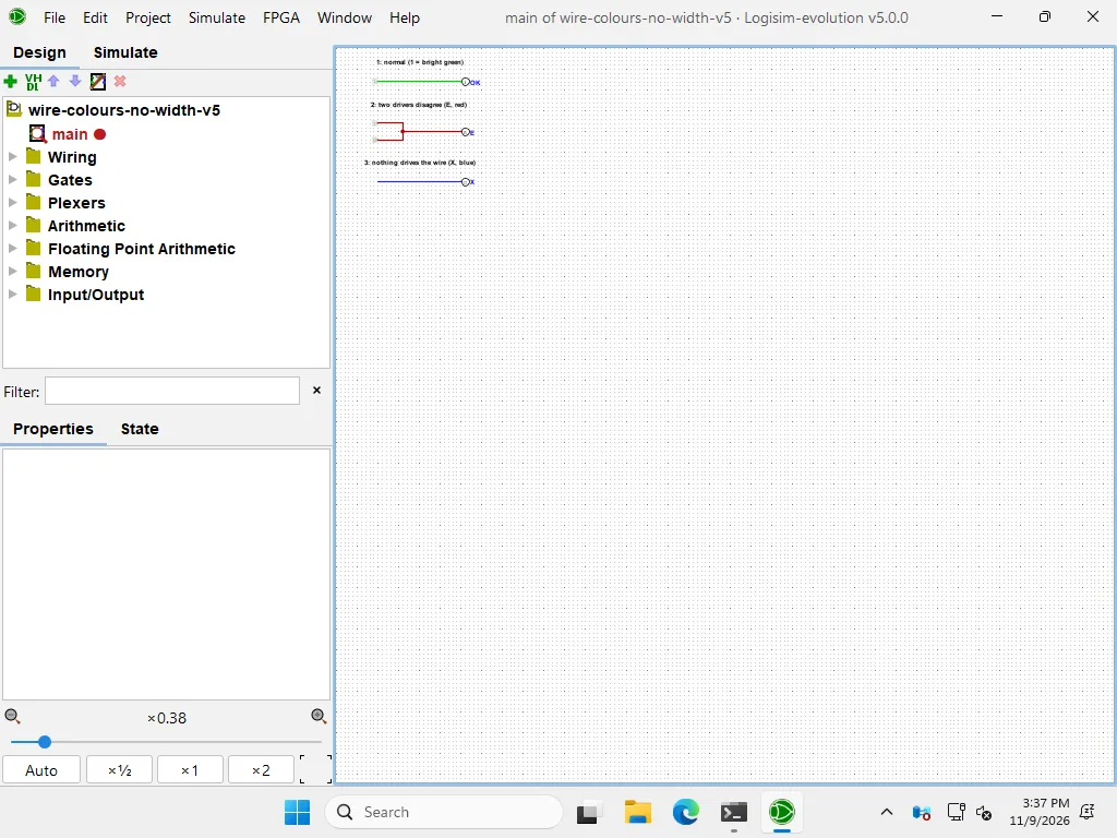
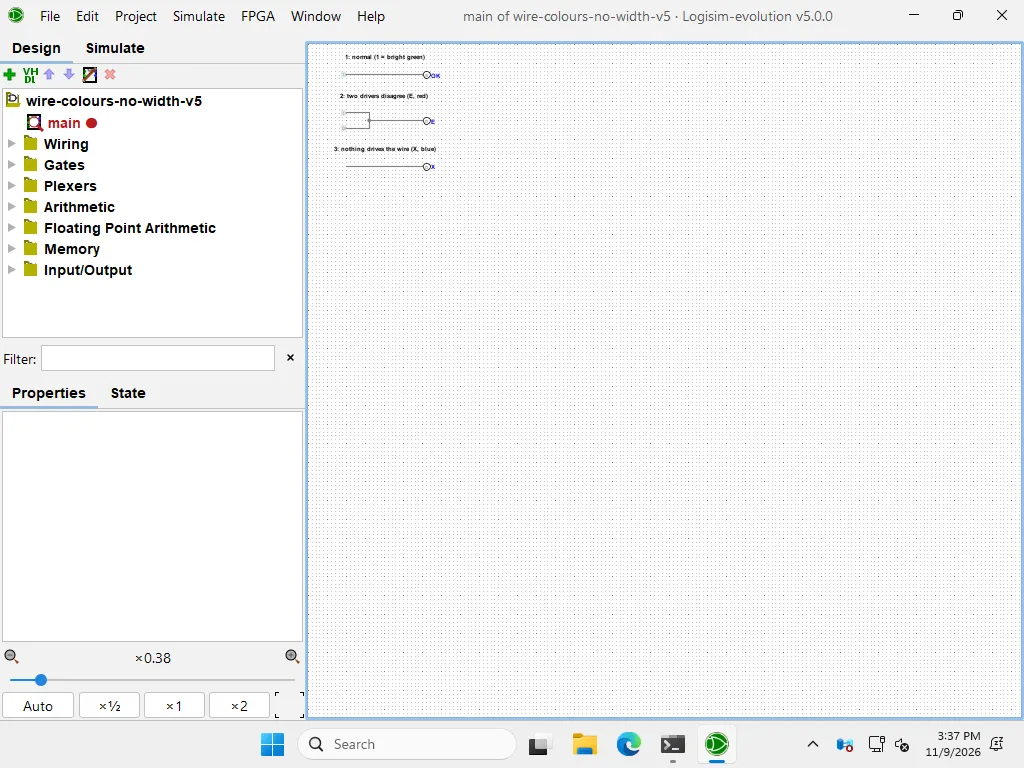
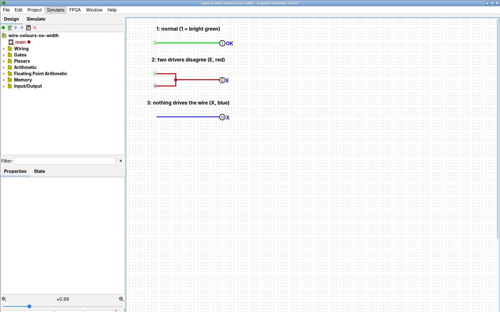
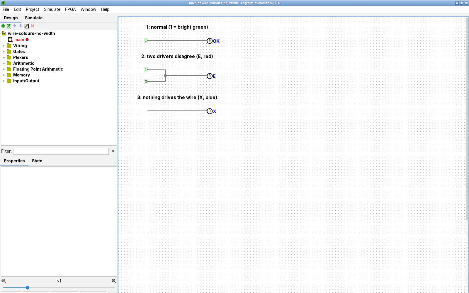
Other reasons for grey wires: Auto-Propagate is switched off (see Clock and simulation), or a wire has nothing attached, which Logisim draws in its Unconnected colour.
Dark green and black: normal
On a one-bit wire, 1 is bright green and 0 is dark green. A wire wider than one bit is drawn thick in the bus colour, and its value shows when you hover or attach a probe, in the radix you choose. See Pins and probes. Only red, blue, orange and grey need action.
Values you see on pins and probes
| Chip | Meaning |
|---|---|
| Low | |
| High | |
| Undriven (X in older documents) | |
| Error: conflict, loop or an error from inside | |
| A multi-bit pin shows one character per bit, so one bad bit stays visible |
Command-line users see the same characters: U and E appear in the table printed by –tty table (command line).
Still stuck? A 5-step check
Then read Oscillation apparent, look up your exact message in the error list, or check the file in the .circ Viewer.
Classic 2.7.1 differences
| Feature | 2.7.1 | 5.0.0 |
|---|---|---|
| Undriven wire shown as | 2.7.1: untestedX in the 2.7.1 documentation | 5.0.0: yesU (F08) |
| Red for conflicts, orange for widths | 2.7.1: untested | 5.0.0: yesseen (F07, F09) |
| Grey until a click after opening a file | 2.7.1: untested | 5.0.0: partialseen with any file (F45, F49) |
| Colour-blind colour preset | 2.7.1: untested | 5.0.0: untested |
Cells say untested where we have no capture from 2.7.1.
Downloads: broken and fixed circuits
Each circuit was checked in Logisim-evolution 5.0.0 against the expected table. The broken ones are checked against the table with E and U written out; the fixed ones with a test vector.
| Circuit | What it shows | Checked by |
|---|---|---|
| circ-wire-colors-showcase.circ (2.7.1 format) | The four cases in one circuit | T-ERR-05 |
| conflict-broken, fixed | Two outputs on one wire, and a multiplexer fix | T-ERR-02 |
| floating-broken, fixed | A wire end that stops short | T-ERR-03 |
| width-broken, fixed | 4-bit into 1-bit, and a splitter fix | T-ERR-04 |
| tristate-bus | Two Controlled Buffers on one wire | T-ERR-06 |
All files are CC BY 4.0. Open any of them in the .circ Viewer to list its widths and unconnected pins.