How TTL chips work in Logisim
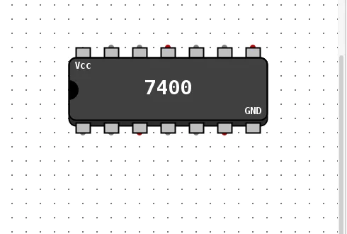
A TTL chip is one component that looks like a DIP package. Its ports follow the real pin numbers: on the default (east) facing, pin 1 is at the bottom left, the numbers rise to the right along the bottom and continue from the right along the top, so the top left is the highest pin, the supply pin. This is how we numbered the pins in every test below. The Vcc and Gnd pins are not ports by default, so a 7400 shows 12 of its 14 pins.
Every chip has the same four attributes: Facing, Enable Vcc and Gnd ports, Show the internal structure, and Label. We read them from the 5.0.0 jar for the 7400, 7447 and 74161.
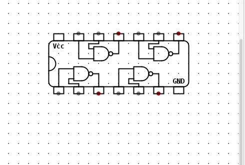
Show the internal structure is a Yes or No choice (default No). With it on, the DIP outline is drawn open: for the 7400 you see the four NAND gates, the Vcc and GND corners and a marker at each pin.
Power pins
Describe this circuit
Components: 7400 1; Input pin p1; Input pin p2; Input pin p4; Input pin p5; Input pin p9; Input pin p10; Input pin p12; Input pin p13; Input pin vcc; Input pin gnd; Output pin p3; Output pin p6; Output pin p8; Output pin p11.
- 7400 1 connects to Input pin p1 (net p1).
- 7400 1 connects to Input pin p2 (net p2).
- 7400 1 connects to Output pin p3 (net p3).
- 7400 1 connects to Input pin p4 (net p4).
- 7400 1 connects to Input pin p5 (net p5).
- 7400 1 connects to Output pin p6 (net p6).
- 7400 1 connects to Output pin p8 (net p8).
- 7400 1 connects to Input pin p9 (net p9).
- 7400 1 connects to Input pin p10 (net p10).
- 7400 1 connects to Output pin p11 (net p11).
- 7400 1 connects to Input pin p12 (net p12).
- 7400 1 connects to Input pin p13 (net p13).
Download circ-ttl-7400-power.circ. It was saved by 5.0.0 and does not open in 2.7.1. Its vector checks the powered rows only; the unpowered result (U) is described above.
Find a chip
| 7400: quad 2-input NAND gate | 2.15.0 | 12 | |
|---|---|---|---|
| 7402: quad 2-input NOR gate (right-to-left) | 2.15.0 | 12 | |
| 7404: hex inverter | 2.15.0 | 12 | |
| 7408: quad 2-input AND gate | 2.15.0 | 12 | |
| 7410: triple 3-input NAND gate | 2.15.0 | 12 | |
| 7411: triple 3-input AND gate | 2.15.0 | 12 | |
| 7413: dual 4-input NAND gate(Schmitt trigger) | 2.15.0 | 10 | |
| 7414: hex inverter (Schmitt trigger) | 2.15.0 | 12 | |
| 7418: dual 4-input NAND gate(Schmitt trigger) | 2.15.0 | 10 | |
| 7419: hex inverter (Schmitt trigger) | 2.15.0 | 12 | |
| 7420: dual 4-input NAND gate | 2.15.0 | 10 | |
| 7421: dual 4-input AND gate | 2.15.0 | 10 | |
| 7424: quad 2-input NAND gate (Schmitt trigger) | 2.15.0 | 12 | |
| 7427: triple 3-input NOR gate | 2.15.0 | 12 | |
| 7430: single 8-input NAND gate | 2.15.0 | 9 | |
| 7432: quad 2-input OR gate | 2.15.0 | 12 | |
| 7434: hex buffer gate | 3.6.0 | 12 | |
| 7436: quad 2-input NOR gate | 2.15.0 | 12 | |
| 7438: quad 2-input NAND gate (open-collector) | 5.0.0 | 12 | yes |
| 7442: BCD to decimal decoder | 2.15.0 | 14 | |
| 7443: Excess-3 to decimal decoder | 2.15.0 | 14 | |
| 7444: Gray to decimal decoder | 2.15.0 | 14 | |
| 7447: BCD to 7-segment decoder | 2.15.0 | 14 | |
| 7451: dual AND-OR-INVERT gate | 2.15.0 | 10 | |
| 7454: Four wide AND-OR-INVERT gate | 2.15.0 | 9 | |
| 7458: dual AND-OR gate | 2.15.0 | 12 | |
| 7464: 4-2-3-2 AND-OR-INVERT gate | 2.15.0 | 12 | |
| 7474: dual D-Flipflops with preset and clear | 2.15.0 | 12 | |
| 7476: dual J-K Flipflops with preset and clear | 5.0.0 | 14 | yes |
| 7485: 4-bit magnitude comparator | 2.15.0 | 14 | |
| 7486: quad 2-input XOR gate | 2.15.0 | 12 | |
| 7487: 4-bit True/complement, zero/one elements | 3.9.0 | 10 | |
| 7493: 4-bit binary ripple counter | 5.0.0 | 8 | yes |
| 74125: quad bus buffer, three-state outputs, negative enable | 2.15.0 | 12 | |
| 74138: 3-line to 8-line decoder | 3.8.0 | 14 | |
| 74139: Dual 2-line to 4-line decoder | 3.6.0 | 14 | |
| 74151: 8-line to 1 line data selector | 3.9.0 | 14 | |
| 74153: dual 4-line to 1 line data selector | 3.9.0 | 14 | |
| 74157: quad 2-line to 1 line data selector | 3.8.0 | 14 | |
| 74158: quad 2-line to 1 line data selector, inverted output | 3.8.0 | 14 | |
| 74161: 4-bit sync counter with async clear | 3.5.0 | 14 | |
| 74163: 4-bit sync counter with sync clear | 3.6.0 | 14 | |
| 74164: 8-bit serial-to-parallel shift register | 3.8.0 | 12 | |
| 74165: 8-bit parallel-to-serial shift register | 2.15.0 | 14 | |
| 74166: 8-bit parallel-to-serial shift register with asynchronous clear | 3.8.0 | 14 | |
| 74173: 4-bit D-type registers with 3-state outputs | 5.0.0 | 14 | yes |
| 74175: quad D-flipflop, asynchronous reset | 2.15.0 | 14 | |
| 74181: arithmetic logic unit | 3.9.0 | 22 | |
| 74182: look-ahead carry generator | 3.9.0 | 14 | |
| 74192: 4-bit up/down decade counter | 3.8.0 | 14 | |
| 74193: 4-bit up/down binary counter | 3.8.0 | 14 | |
| 74194: 4-bit bidirectional universal shift register | 4.0.0 | 14 | |
| 74240: octal buffers with three-state inverted outputs | 3.8.0 | 18 | |
| 74241: octal buffers with three-state outputs and complementary enables | 3.8.0 | 18 | |
| 74244: octal buffers with three-state outputs | 3.8.0 | 18 | |
| 74245: octal bus transceivers with three-state outputs | 3.8.0 | 18 | |
| 74266: quad 2-input XNOR gate (open-collector) | 3.8.0 | 12 | |
| 74273: octal D-Flipflop with clear | 2.15.0 | 18 | |
| 74283: 4-bit binary full adder | 2.15.0 | 14 | |
| 74299: 8-bit universal shift register with three-state outputs | 3.9.0 | 18 | |
| 74377: octal D-Flipflop with enable | 2.15.0 | 18 | |
| 74381: arithmetic logic unit (ALU) | 3.9.0 | 18 | |
| 74541: Octal buffers with three-state outputs | 3.9.0 | 18 | |
| 74670: 4-by-4 register file with three-state outputs | 3.9.0 | 14 | |
| 747266: quad 2-input XNOR gate | 2.15.0 | 12 |
No chips match.
The built-in equivalents are the gates for the 74xx gate chips, the decoder and multiplexers for the 74138, 74139, 74151 and 74153, the counter for the 74161, and the registers for the 74173 and 74194. The 74181 has no single built-in equivalent.
Chips people ask about
7400 quad NAND
loc Logisim storesPorts as a table
| # | Port | Direction | Width | Offset from anchor |
|---|---|---|---|---|
| 1 | Input | in | 1 | (10, 30) |
| 2 | Input | in | 1 | (30, 30) |
| 3 | Output | out | 1 | (50, 30) |
| 4 | Input | in | 1 | (70, 30) |
| 5 | Input | in | 1 | (90, 30) |
| 6 | Output | out | 1 | (110, 30) |
| 7 | Output | out | 1 | (130, -30) |
| 8 | Input | in | 1 | (110, -30) |
| 9 | Input | in | 1 | (90, -30) |
| 10 | Output | out | 1 | (70, -30) |
| 11 | Input | in | 1 | (50, -30) |
| 12 | Input | in | 1 | (30, -30) |
Download circ-ttl-7400-nand.circ. Pins 1 and 2 feed pin 3, pins 4 and 5 feed pin 6, pins 9 and 10 feed pin 8, and pins 12 and 13 feed pin 11.
74161 counter
loc Logisim storesPorts as a table
| # | Port | Direction | Width | Offset from anchor |
|---|---|---|---|---|
| 1 | Input 1 | in | 1 | (10, 30) |
| 2 | Input 2 | in | 1 | (30, 30) |
| 3 | Input 3 | in | 1 | (50, 30) |
| 4 | Input 4 | in | 1 | (70, 30) |
| 5 | Input 5 | in | 1 | (90, 30) |
| 6 | Input 6 | in | 1 | (110, 30) |
| 7 | Input 7 | in | 1 | (130, 30) |
| 8 | Input 9 | in | 1 | (150, -30) |
| 9 | Input 10 | in | 1 | (130, -30) |
| 10 | Output 11 | out | 1 | (110, -30) |
| 11 | Output 12 | out | 1 | (90, -30) |
| 12 | Output 13 | out | 1 | (70, -30) |
| 13 | Output 14 | out | 1 | (50, -30) |
| 14 | Output 15 | out | 1 | (30, -30) |
Pin 1 is the active-low clear, pin 2 the clock, pins 3 to 6 the data inputs, pin 7 and pin 10 the enables, pin 9 the active-low load, pins 14 to 11 the outputs from low to high bit, and pin 15 the carry.
Download circ-ttl-74161-counter.circ. The vector uses the set and seq columns, because each row builds on the last (test vectors). The built-in Counter is simpler when you do not need the chip.
74181 ALU
loc Logisim storesPorts as a table
| # | Port | Direction | Width | Offset from anchor |
|---|---|---|---|---|
| 1 | Input 1 | in | 1 | (10, 30) |
| 2 | Input 2 | in | 1 | (30, 30) |
| 3 | Input 3 | in | 1 | (50, 30) |
| 4 | Input 4 | in | 1 | (70, 30) |
| 5 | Input 5 | in | 1 | (90, 30) |
| 6 | Input 6 | in | 1 | (110, 30) |
| 7 | Input 7 | in | 1 | (130, 30) |
| 8 | Input 8 | in | 1 | (150, 30) |
| 9 | Output 9 | out | 1 | (170, 30) |
| 10 | Output 10 | out | 1 | (190, 30) |
| 11 | Output 11 | out | 1 | (210, 30) |
| 12 | Output 13 | out | 1 | (230, -30) |
| 13 | Output 14 | out | 1 | (210, -30) |
| 14 | Output 15 | out | 1 | (190, -30) |
| 15 | Output 16 | out | 1 | (170, -30) |
| 16 | Output 17 | out | 1 | (150, -30) |
| 17 | Input 18 | in | 1 | (130, -30) |
| 18 | Input 19 | in | 1 | (110, -30) |
| 19 | Input 20 | in | 1 | (90, -30) |
| 20 | Input 21 | in | 1 | (70, -30) |
| 21 | Input 22 | in | 1 | (50, -30) |
| 22 | Input 23 | in | 1 | (30, -30) |
Download circ-ttl-74181-alu.circ with a 1,024-row vector. Data pins that carry an overbar on a printed datasheet are plain active-high inputs here.
7447 BCD to 7-segment decoder
loc Logisim storesPorts as a table
| # | Port | Direction | Width | Offset from anchor |
|---|---|---|---|---|
| 1 | Input 1 | in | 1 | (10, 30) |
| 2 | Input 2 | in | 1 | (30, 30) |
| 3 | Input 3 | in | 1 | (50, 30) |
| 4 | Input/Output 4 | in-out | 1 | (70, 30) |
| 5 | Input 5 | in | 1 | (90, 30) |
| 6 | Input 6 | in | 1 | (110, 30) |
| 7 | Input 7 | in | 1 | (130, 30) |
| 8 | Output 9 | out | 1 | (150, -30) |
| 9 | Output 10 | out | 1 | (130, -30) |
| 10 | Output 11 | out | 1 | (110, -30) |
| 11 | Output 12 | out | 1 | (90, -30) |
| 12 | Output 13 | out | 1 | (70, -30) |
| 13 | Output 14 | out | 1 | (50, -30) |
| 14 | Output 15 | out | 1 | (30, -30) |
The outputs are active low. In our sweep, digits 0 to 9 drew 6 without its top segment, 7 as a, b and c only and 9 without its bottom segment. Lamp test (pin 3 low) lit all seven segments, blanking input (pin 4 low) turned all seven off, and ripple blanking input (pin 5 low) blanked only a zero. See the 7-segment page for the display side.
Describe this circuit
Components: 7447 1; 7447 2; Input pin hp7; Input pin hp1; Input pin hp2; Input pin hp6; Input pin hp3; Input pin hp5; Input pin lp7; Input pin lp1; Input pin lp2; Input pin lp6; Input pin lp3; Output pin hp4; Output pin lp4; Output pin lp13; Output pin lp12; Output pin lp11; Output pin lp10; Output pin lp9; Output pin lp15; Output pin lp14.
- 7447 1 connects to Input pin hp1 (net hp1).
- 7447 1 connects to Input pin hp2 (net hp2).
- 7447 1 connects to Input pin hp3 (net hp3).
- 7447 1 connects to 7447 2, Output pin hp4 (net hp4).
- 7447 1 connects to Input pin hp5 (net hp5).
- 7447 1 connects to Input pin hp6 (net hp6).
- 7447 1 connects to Input pin hp7 (net hp7).
- 7447 2 connects to Input pin lp1 (net lp1).
- 7447 2 connects to Input pin lp2 (net lp2).
- 7447 2 connects to Input pin lp3 (net lp3).
- 7447 2 connects to Output pin lp4 (net lp4).
- 7447 2 connects to Input pin lp6 (net lp6).
- 7447 2 connects to Input pin lp7 (net lp7).
- 7447 2 connects to Output pin lp9 (net lp9).
- 7447 2 connects to Output pin lp10 (net lp10).
- 7447 2 connects to Output pin lp11 (net lp11).
- 7447 2 connects to Output pin lp12 (net lp12).
- 7447 2 connects to Output pin lp13 (net lp13).
- 7447 2 connects to Output pin lp14 (net lp14).
- 7447 2 connects to Output pin lp15 (net lp15).
Download circ-ttl-7447-two-digit-blanking.circ.
74138 3-to-8 decoder
loc Logisim storesPorts as a table
| # | Port | Direction | Width | Offset from anchor |
|---|---|---|---|---|
| 1 | Input 1 | in | 1 | (10, 30) |
| 2 | Input 2 | in | 1 | (30, 30) |
| 3 | Input 3 | in | 1 | (50, 30) |
| 4 | Input 4 | in | 1 | (70, 30) |
| 5 | Input 5 | in | 1 | (90, 30) |
| 6 | Input 6 | in | 1 | (110, 30) |
| 7 | Output 7 | out | 1 | (130, 30) |
| 8 | Output 9 | out | 1 | (150, -30) |
| 9 | Output 10 | out | 1 | (130, -30) |
| 10 | Output 11 | out | 1 | (110, -30) |
| 11 | Output 12 | out | 1 | (90, -30) |
| 12 | Output 13 | out | 1 | (70, -30) |
| 13 | Output 14 | out | 1 | (50, -30) |
| 14 | Output 15 | out | 1 | (30, -30) |
Pins 1 to 3 are the address (A is pin 1), pins 4 and 5 are the two active-low enables, pin 6 is the active-high enable, and pins 15 down to 9 and pin 7 are the active-low outputs Y0 to Y7 (Y0 is pin 15, Y7 is pin 7).
Download circ-ttl-74138-decoder.circ.
74194 shift register
loc Logisim storesPorts as a table
| # | Port | Direction | Width | Offset from anchor |
|---|---|---|---|---|
| 1 | Input 1 | in | 1 | (10, 30) |
| 2 | Input 2 | in | 1 | (30, 30) |
| 3 | Input 3 | in | 1 | (50, 30) |
| 4 | Input 4 | in | 1 | (70, 30) |
| 5 | Input 5 | in | 1 | (90, 30) |
| 6 | Input 6 | in | 1 | (110, 30) |
| 7 | Input 7 | in | 1 | (130, 30) |
| 8 | Input 9 | in | 1 | (150, -30) |
| 9 | Input 10 | in | 1 | (130, -30) |
| 10 | Input 11 | in | 1 | (110, -30) |
| 11 | Output 12 | out | 1 | (90, -30) |
| 12 | Output 13 | out | 1 | (70, -30) |
| 13 | Output 14 | out | 1 | (50, -30) |
| 14 | Output 15 | out | 1 | (30, -30) |
Pin 1 is the active-low clear, pin 2 the shift-right serial input, pins 3 to 6 the parallel inputs A to D, pin 7 the shift-left serial input, pins 9 and 10 the mode inputs S0 and S1, pin 11 the clock, and pins 15 to 12 the outputs QA to QD.
Download circ-ttl-74194-shift-register.circ.
74245 bus transceiver
loc Logisim storesPorts as a table
| # | Port | Direction | Width | Offset from anchor |
|---|---|---|---|---|
| 1 | Input 1 | in | 1 | (10, 30) |
| 2 | Input/Output 2 | in-out | 1 | (30, 30) |
| 3 | Input/Output 3 | in-out | 1 | (50, 30) |
| 4 | Input/Output 4 | in-out | 1 | (70, 30) |
| 5 | Input/Output 5 | in-out | 1 | (90, 30) |
| 6 | Input/Output 6 | in-out | 1 | (110, 30) |
| 7 | Input/Output 7 | in-out | 1 | (130, 30) |
| 8 | Input/Output 8 | in-out | 1 | (150, 30) |
| 9 | Input/Output 9 | in-out | 1 | (170, 30) |
| 10 | Input/Output 11 | in-out | 1 | (190, -30) |
| 11 | Input/Output 12 | in-out | 1 | (170, -30) |
| 12 | Input/Output 13 | in-out | 1 | (150, -30) |
| 13 | Input/Output 14 | in-out | 1 | (130, -30) |
| 14 | Input/Output 15 | in-out | 1 | (110, -30) |
| 15 | Input/Output 16 | in-out | 1 | (90, -30) |
| 16 | Input/Output 17 | in-out | 1 | (70, -30) |
| 17 | Input/Output 18 | in-out | 1 | (50, -30) |
| 18 | Input 19 | in | 1 | (30, -30) |
Pin 1 is the direction input, pins 2 to 9 are the A side, pins 18 to 11 the B side, and pin 19 the active-low output enable.
Other chips
We did not test the other 59 chips. Their ports are measured; their behaviour is not.
New and fixed in 5.0.0
Our component data lists four chips with the version 5.0.0: the 7438, 7476, 7493 and 74173. The 7447 pin 4 behaviour above is the case we tested ourselves. Twenty more chips exist on the upstream main branch but not in 5.0.0, so they are not listed here.
Missing a chip?
Use the built-in equivalent, or build the chip as a subcircuit. The 7473 is not in the library: use the 7476, a J-K flip-flop with preset and clear, or two J-K Flip-Flops. Chips can also come from an external library; see libraries.
Version differences
| Feature | 2.7.1 | 5.0.0 |
|---|---|---|
| TTL library | 2.7.1: nonone in 2.7.1 (F23) | 5.0.0: yes65 chips |
| 7447 BI/RBO as a bidirectional pin | 2.7.1: nono TTL library | 5.0.0: yescascade tested (F113); failed in 4.1.0 |
| Enable Vcc and Gnd ports | 2.7.1: nono TTL library | 5.0.0: yestested (F115) |
Chips by the release that introduced them, from our component data (the 20 unreleased entries are not counted):
| 2.15.0 | 35 |
|---|---|
| 3.5.0 | 1 |
| 3.6.0 | 3 |
| 3.8.0 | 12 |
| 3.9.0 | 9 |
| 4.0.0 | 1 |
| 5.0.0 | 4 |
No rows match.
See also all components and the ALU project, which uses the 74181.