Clock not ticking? Check these four things
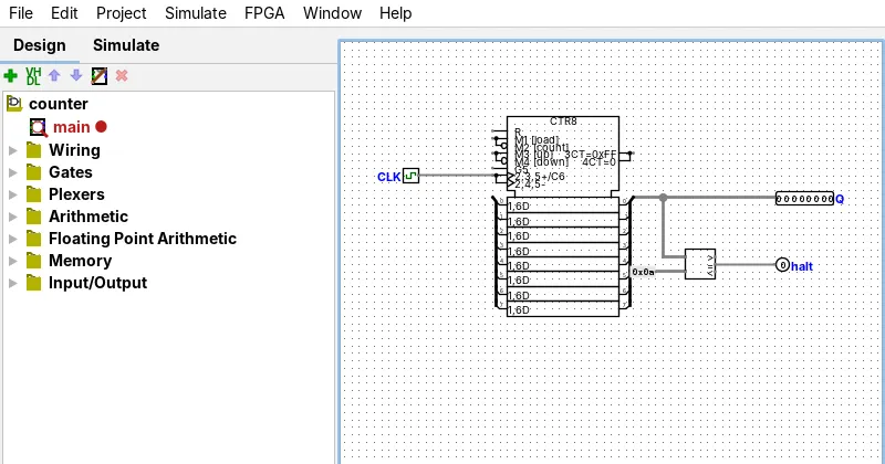
Some users report on GitHub that a clock only changed when clicked, on a 3.9.0 aarch64 build (issue 1453). That is a community report, and we did not reproduce it.
Propagation and ticks: two different things
Propagation is values flowing through gates until they are stable. It happens whenever an input changes, and Auto-Propagate and Single-Step Propagation control it. Ticks are the Clock component flipping between 0 and 1. Auto-Tick and the manual tick commands control those. A circuit with a clock needs both: a tick changes the clock, and propagation carries the change to the flip-flops and counters.
One tick is half a cycle (one clock edge), and a full cycle is two ticks.
Every control in the Simulate menu
| Menu item | Shortcut | What it does |
|---|---|---|
| Auto-Propagate | CtrlE⌘E (⌘E on macOS) | Recomputes values whenever something changes. Ticked by default. |
| Single-Step Propagation | CtrlI⌘I (⌘I on macOS) | Advances propagation one step at a time, so you can watch a value travel. |
| Reset Simulation | CtrlR⌘R (⌘R on macOS) | Returns flip-flops, registers and memory to their starting values and recomputes. |
| VHDL Simulation Enabled | none | Switches VHDL entity simulation on (needs an external simulator). |
| Restart VHDL simulator | none | Restarts that simulator. |
| Go Out To State, Go In To State | none | Moves between a subcircuit’s state and its parent’s. Greyed in our screenshot, where no subcircuit was selected. See Subcircuits. |
| Manual Tick Half Cycle | CtrlT⌘T (⌘T on macOS) | One clock edge. |
| Manual Tick Full Cycle | CtrlF9⌘F9 (⌘F9 on macOS) | Two clock edges: a full 0, 1, 0 cycle. |
| Auto-Tick Enabled | CtrlK⌘K (⌘K on macOS) | Ticks the clock continuously. |
| Auto-Tick Frequency | submenu | The speed of automatic ticks. |
| Timing diagram | none | Opens the timing diagram. See Timing diagram. |
| Test Vector… | none | Runs a test vector. See Test vectors. |
| Assembly viewer | none | Viewer for assembly programs in a system-on-chip design. |
The shortcuts are as shown in the 5.0.0 menus on Linux and Windows (F46). On a Mac the same items use Command (F62):
The Simulate tab on the left has toolbar buttons for the same actions: Run simulator continuously, Step simulator once, Tick clock one half cycle, Tick clock one full cycle, and Enable or Disable clock ticks (the tooltip texts in the 5.0.0 string table, F73).
In our test (F81), Ctrl+T changed the circuit and a second Ctrl+T changed it again, and Ctrl+K made it keep changing with no further input.
Choosing a clock frequency
Auto-Tick Frequency is a submenu of preset speeds. We did not measure the rate the window actually reaches, so we give no window figures here. The window draws every change, which costs time. To see what the window reaches on your machine, turn on Show tick rate in the Preferences.
For a command-line run there are numbers. A 16-bit counter that counts to 65,535 (131,069 ticks) ran at these speeds with --tty speed (F19):
5.0.0 ran about 3.5 times faster than classic 2.7.1 on the same machine and Java.
Show the data
| Item | kHz | Note |
|---|---|---|
| 5.0.0, Linux lab (run 1) | 405 | |
| 5.0.0, Linux lab (run 2) | 427 | |
| 5.0.0, Linux lab (run 3) | 465 | |
| 5.0.0, Windows x64 runner | 496 | |
| 5.0.0, Windows ARM64 runner | 526 | |
| 2.7.1, Linux lab (run 1) | 122 | |
| 2.7.1, Linux lab (run 2) | 138 | |
| 2.7.1, Linux lab (run 3) | 112 |
F19
Command-line benchmark, not the window. Values rounded to kHz. A later run of the file below on the Linux lab gave 496 kHz (F82): speeds vary with load.
The benchmark circuit is a download: circ-clock-and-simulation-benchmark.circ. Run it with java -jar logisim-evolution-5.0.0-all.jar --tty speed circ-clock-and-simulation-benchmark.circ.
Half tick vs full tick
One tick is one clock edge: the clock goes from 0 to 1, or from 1 to 0. A full cycle is two ticks. A counter that counts on the rising edge changes once per full cycle, so pressing Ctrl+T once changes the clock but may not change the counter. Press it twice, or press Ctrl+F9 once.
If a counter seems to count twice per cycle, check the flip-flop or counter’s Trigger attribute: Rising Edge counts once per cycle, and a level setting can count many times while the clock stays high (see oscillation and counters).
Simulation looks stuck or paused
Try these in this order:
- Click once anywhere on the canvas, or press CtrlR⌘R (⌘R on macOS). After opening any file in 5.0.0, every wire stays grey and the pins show 0 until the first click or a reset. Moving the mouse does not help. We saw this on a Linux lab machine, a Windows desktop and a macOS 15 machine (F03, F45, F49, F64). See grey wires.
- Check Auto-Propagate (CtrlE⌘E (⌘E on macOS)). If it is off, nothing recomputes.
- Check Auto-Tick Enabled (CtrlK⌘K (⌘K on macOS)). With it off, a clock never moves by itself (F81).
- Look for red wires. A loop that never settles stops the simulation. See Oscillation apparent.
- Check which view you have open. The static layout of a subcircuit is not its running state; use Go In To State from the parent circuit.
Reset: what it clears
Reset Simulation returns flip-flops, registers and counters to their starting values and recomputes the circuit. It does not stop ticking or change your wiring. Memory contents start at 0 by default, according to the Logisim-evolution documentation, and an option makes memory start unknown or random instead; we did not test that option. For a design that needs a reset pulse at power-up, there is a Power-On Reset component (POR).
Stopping or gating the clock
To stop a counter or register, give it an enable and lower the enable. Our circuit uses the counter’s Enable pin: while EN is 0, the clock edges change nothing, and the count resumes when EN returns to 1.
Describe this circuit
Components: Input pin CLK; Input pin EN; Counter 1; Output pin Q.
- Input pin CLK connects to Counter 1 (net CLK).
- Input pin EN connects to Counter 1 (net EN).
- Counter 1 connects to Output pin Q (net Q), 8 bits wide.
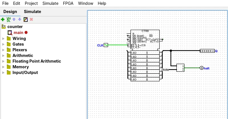
For command-line runs, add a pin labelled halt: the run ends when it goes high. Our counter example stops when a comparator sees the count 10:
Describe this circuit
Components: Clock CLK; Counter 1; Comparator 1; Constant 1; Output pin Q; Output pin halt.
- Clock CLK connects to Counter 1.
- Counter 1 connects to Comparator 1, Output pin Q (net Q), 8 bits wide.
- Comparator 1 connects to Constant 1, 8 bits wide.
- Comparator 1 connects to Output pin halt (net halt).
Running a circuit without the window
Two forms cover most needs: --tty table prints a truth table, or the state per tick when the circuit has a clock and a halt pin; --tty speed prints how fast the circuit ran. See command line. Both ran on a machine with no display; --test-vector does not (F18).
Classic 2.7.1 differences
| Feature | 2.7.1 | 5.0.0 |
|---|---|---|
| Menu names | 2.7.1: untestedTicks Enabled, Tick Once, Tick Frequency in its documentation | 5.0.0: yesAuto-Tick Enabled, Manual Tick Half Cycle and Full Cycle, Auto-Tick Frequency |
| Command-line speed (16-bit counter) | 2.7.1: partial112 to 138 kHz (F19) | 5.0.0: yes405 to 465 kHz (F19) |
| Single-Step Propagation | 2.7.1: untested | 5.0.0: yesCtrl+I (F46) |
| Timing diagram | 2.7.1: no | 5.0.0: yesSimulate menu (F46) |
Cells say untested where we have no 2.7.1 capture.
Downloads
All three are CC BY 4.0 and open in the .circ Viewer.
| Circuit | What it shows | Checked by |
|---|---|---|
| circ-clock-and-simulation-counter.circ | Clock, counter and a halt pin | --tty table prints the expected 11 rows |
| circ-clock-and-simulation-enable.circ | A counter stopped by Enable, not by gating the clock | Sequential test vector, 10 rows |
| circ-clock-and-simulation-benchmark.circ | The 16-bit speed benchmark | --tty speed runs 131,069 ticks |
The VHDL simulator items in the Simulate menu are covered in VHDL and Verilog.